1. What is Spectral Response?
Spectral response refers to the output of a detection device in response to incident light of different wavelengths. The spectral response curve is obtained by plotting test data across the entire operating wavelength range of the detection device.
When the device's output is expressed as an absolute physical quantity (such as current, voltage, or other dimensional quantities), it is called an absolute spectral response curve. If dimensionless processing such as normalization has been performed, it is generally called a relative spectral response curve. The following figure shows the spectral response curves of two different types of photodetectors.
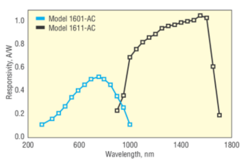
Spectral response curves provide a clear understanding of a device's response across different wavelength ranges, crucial for flexible equipment use and accurate test result interpretation.
2. Infrared Imaging
All techniques utilizing infrared radiation for imaging are called infrared imaging technologies. These mainly include passive imaging and active imaging.
Passive imaging refers to imaging without artificial infrared illumination, relying solely on receiving infrared radiation signals emitted/reflected by the object itself, such as traditional thermal imaging.
Active imaging utilizes artificial infrared illumination and images the infrared signals reflected back from the object.
Infrared imaging equipment covers a wide wavelength range, such as 0.7µm-30µm, from near-infrared, short-wave infrared, mid-wave infrared to long-wave infrared, very long-wave infrared, and far-infrared.
The classification of spectral ranges varies across industries and fields; however, the 0.7µm-30µm range is commonly used as the operating wavelength for infrared imaging equipment, representing the vast majority of application scenarios.
3. Measurement System and Principle
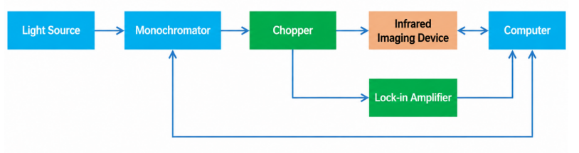
The entire testing system is shown in the figure below. The broadband light emitted by the light source is converted into light of a single predominant wavelength by a monochromator before being incident on the infrared imaging device under test. The computer records the corresponding output value of the infrared imaging device.
If the optical power output by the light source is too low in a certain wavelength band, a phase-locked loop (PLL) system can be used to improve the detection sensitivity of weak light signals. Specifically, the optical signal is modulated by a chopper before entering the device under test. The LPL amplifier is connected to the chopper to acquire the frequency information of the signal modulation, and the signal value is then obtained on the computer.
(1) Light Source
To measure the spectral response of an infrared imaging device, a broadband light source is required to cover the range of the spectrum to be measured. A blackbody radiation source is usually the preferred choice. A blackbody radiation source can radiate a broadband light source by heating it through a cavity, the center wavelength shifts towards shorter wavelengths as the temperature increases. See the figure below.
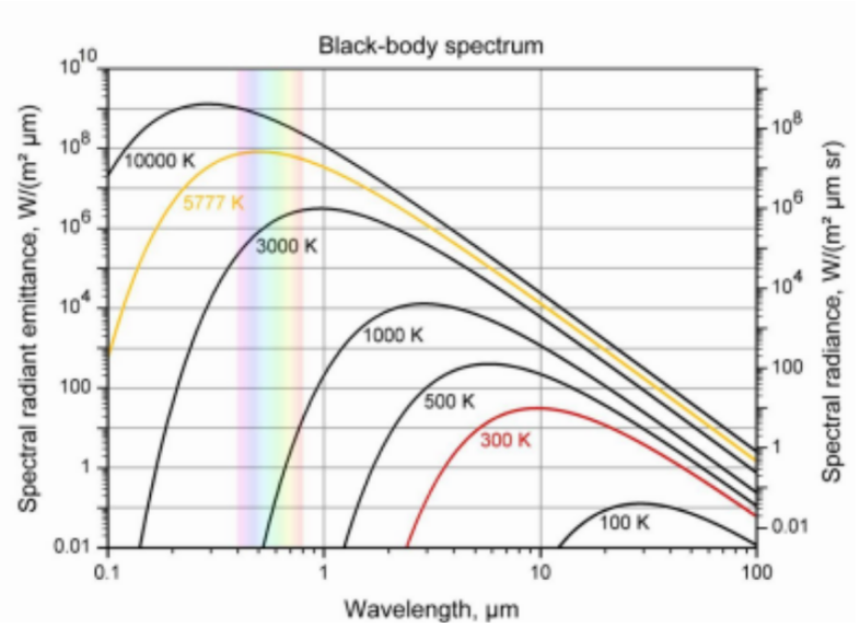
To generate light signals with wavelengths smaller than 1µm through blackbody radiation, high temperatures are required. Such high-temperature blackbody radiation sources (around 3000K and above) are expensive. Deuterium lamps and halogen tungsten lamps can be used as alternatives, combined with the blackbody radiation source.
(2) Monochromator
The function of a monochromator is to filter out different single wavelengths from the broadband light emitted by the light source. Due to the extremely wide spectral range of the light source, the monochromator requires multiple gratings to switch and cover the wavelength range.
In addition, a reflective optical system should be used as much as possible for the monochromator, because the material of the lens has a significant impact on the infrared band, which is not conducive to measurement.
(3) Others
Infrared imaging equipment generally has parameter settings such as integration time. During the measurement process, it is important to maintain the consistency of parameter settings. If parameters change, equivalent conversions should be performed.
Furthermore, for tests using multiple light sources spliced together, cross-overlap tests should be performed at the splicing wavelengths to maintain test consistency when testing different light sources.
Share