The RS485 bus offers numerous advantages, including a simple structure, long communication distances, high communication speeds, and low cost. It is widely utilized in industries such as industrial communication, power monitoring, and instrumentation. However, due to the harsh nature of industrial control environments, communication lines are prone to increased interference coupling, which can compromise the reliability of the RS485 bus and even damage the RS485 transceiver chips. Electrical Fast Transient (EFT) interference—also known as pulse burst interference—is a common form of such disturbance. Consequently, Electrical Fast Transient (EFT) immunity testing is typically employed to simulate this interference and validate the reliability of the system.
Sources of Pulse Burst Interference
In industrial control environments, transient interference frequently arises from events such as lightning strikes, short circuits, and switching operations involving inductive loads. These disturbances manifest as brief, high-energy pulse transients characterized by their tendency to appear in clusters, extremely short rise times, and high repetition frequencies.
These disturbances can couple onto the RS485 bus. Since these transients do not occur as isolated pulses but rather as a continuous series, they generate a cumulative effect on the bus. This accumulation causes the voltage amplitude of the disturbance to exceed the noise margin of the RS485 transceiver, thereby triggering communication errors.
Furthermore, due to the short duration of these pulse transients—specifically the brief intervals between individual pulses—a subsequent pulse often arrives before the preceding one has fully dissipated. Consequently, the parasitic capacitance on the RS485 bus and the junction capacitance within the RS485 transceiver begin recharging before they have had sufficient time to fully discharge. Given that these parasitic capacitances are typically quite small, even a relatively low amount of energy can drive the voltage to very high levels; this makes the RS485 transceiver susceptible to damage and ultimately undermines the reliability of RS485 bus communication.
Mechanism of Pulse Burst Interference Generation
The voltage magnitude of the pulse burst interference source is determined by various factors, including the inductance of the load circuit and the speed at which the load is disconnected. Taking the switching action as an example: because the distance between the fixed and moving contacts is relatively small at the precise moment the switch opens, the back electromotive force (back-EMF) induced by the circuit's inductance is sufficient to break down the air gap between the contacts. Consequently, the circuit begins to conduct. However, this discharge process is extremely brief; during this interval, the circuit generates a high-voltage transient pulse characterized by a rise time in the nanosecond range, a pulse width reaching tens of nanoseconds, and an amplitude exceeding several thousand volts.
Once the aforementioned pulse subsides, the circuit begins to repeat the cycle: the inductive load generates a back-EMF, followed by a discharge across the air gap between the switch's fixed and moving contacts.
This process continues until the energy stored within the inductive load has dissipated to a sufficiently low level—specifically, until it is no longer capable of sustaining the aforementioned discharge process. These disturbances can couple onto the RS485 bus, creating significant interference that ultimately compromises the reliability of communication.
Measures to Enhance Immunity to Electrical Fast Transient Bursts
Electrical Fast Transient (EFT) bursts constitute a form of common-mode interference; as such, they can be suppressed through the use of filtering, absorption, or isolation techniques. These measures can be broadly categorized into the following five methods:
[I] RS485 Bus Isolation
(1) Ensuring Equipment and Personal Safety—The Impact of High Voltage
The RS485 standard is utilized for communication between various devices. In many instances, product developers are entirely unaware of the specific type of equipment with which their own device will ultimately interface. Should the counterpart device happen to employ a rudimentary, low-cost capacitive-resistive step-down circuit—reducing 220V AC to 12V DC without any galvanic isolation from the power grid—the processes of testing, debugging, and actual operation become extremely hazardous. Furthermore, if the insulation within a high-voltage device fails, allowing high voltage to be imposed directly onto the RS485 lines, it poses a grave threat to both the integrity of the equipment and the safety of personnel.
(2) Preventing Remote Reception Anomalies—The Impact of Potential Differences
In numerous real-world applications, communication distances can extend to several kilometers, resulting in significant physical separation between individual nodes. Designers often elect to connect the reference ground of each node directly to the local earth ground, utilizing it as the return path for the signal. While this approach may appear to be a normal and reliable practice, the actual earth ground does not constitute an ideal "0" potential reference; rather, the earth acts as a conductor and possesses inherent impedance.
Consequently, when substantial currents flow through the earth, a measurable potential difference will inevitably arise between the two points of the earth ground through which the current is passing. For example, as shown in Figure 1 below, because the distance between points A and B is significant, the potential difference between the reference grounds is not zero, nor is the impedance of the ground line zero. Consequently—due to the effects of the current loop—the voltage at point A is Vs, whereas at point B, it becomes Vc + Vs.
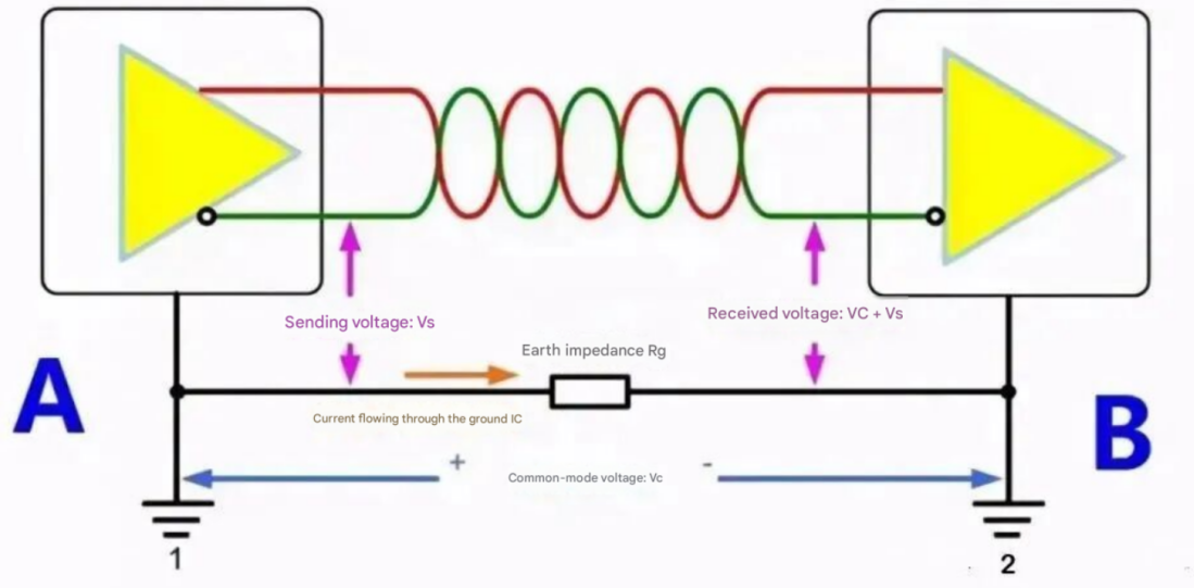
Figure 1. The Effect of Potential Difference
(3) Avoiding Data Anomalies and Component Damage—The Impact of Ground Loops
Since a potential difference exists between the grounds of different nodes, wouldn't it suffice to simply connect the two nodes' grounds directly using a single wire? Absolutely not! Doing so would only exacerbate the situation; this long conductor would form a massive ground loop in conjunction with the earth! As you likely learned during your student days, a closed coil placed within a changing magnetic field will generate an electric current.
50 Hz AC power lines, large electric motors, and similar sources all generate alternating magnetic fields. If a communication bus runs near or passes through such areas, the ground loop can induce currents reaching several amperes—or even hundreds of amperes.
The common-mode voltage generated by the current flowing through this ground loop disrupts the bus's normal communication. Furthermore, beyond steady-state magnetic fields, transient disturbances—such as power line surges, lightning strikes, and high-frequency noise—can be picked up by this colossal "loop antenna," leading to communication anomalies.
[II] Incorporating Ferrite Rings to Absorb Interference
Adding a ferrite ring at the equipment's input interface can effectively absorb interference. Moreover, increasing the number of turns the communication cable makes through the ferrite ring enhances this interference-absorption effect. As illustrated in Figure 2, a ferrite ring is installed near the RS-485 interface of the Device Under Test (DUT).
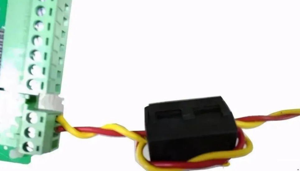
Figure 2. Ferrite Ring Added to Communication Line
[Ⅲ] Use of Shielded Twisted-Pair Cable
As shown in the figure, in practical applications, shielded twisted-pair cables can be used for RS485 communication lines; furthermore, connecting the shielding layer to ground at a single point effectively suppresses the coupling of electrical fast transient bursts onto the communication lines.
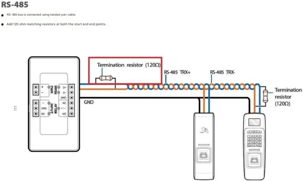
Figure 3. Using Shielded Twisted Pair
[Ⅳ] Adding RS-485 Bus-to-Ground TVS Protection
When TVS diodes are installed between the A-line and ground, and the B-line and ground, any high-amplitude electrical fast transient (EFT) disturbance voltages coupled onto the RS-485 bus will be clamped by the TVS diodes, thereby achieving the objective of protecting the RS-485 transceiver.
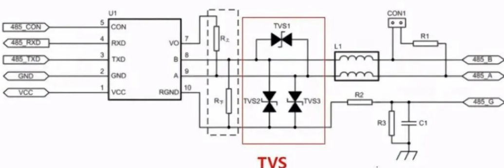
Figure 4. Add a TVS diode for overvoltage protection
[V] Series Ferrite Beads on the RS-485 Bus
Since a ferrite bead acts as a resistor at high frequencies, it converts high-frequency energy into thermal energy, thereby dissipating it. Consequently, when ferrite beads are connected in series on an RS-485 bus, any energy from electrical fast transient (EFT) bursts—should they couple onto the bus—is absorbed and dissipated by the beads, thereby enhancing the RS-485 bus's immunity to interference.
Share