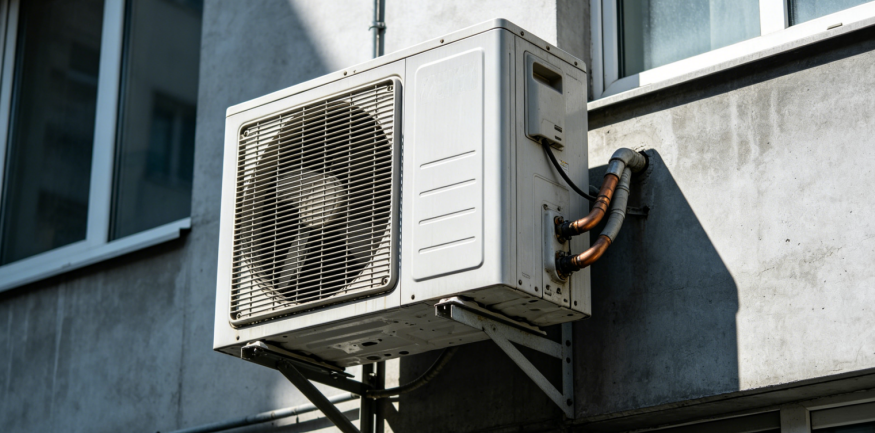
With the accelerating adoption of A2L-class low-GWP refrigerants—such as R32, R454B, and R1234yf—in air conditioning and heat pump applications, refrigerant leak detection sensors have shifted from being "optional features" to "mandatory compliance requirements." The standard GB/T 4706.32-2024, effective August 1, 2026, explicitly mandates that air conditioning systems utilizing A2L refrigerants must be equipped with leak detection sensors that meet the new standard's specifications; these sensors must comply with detailed requirements regarding detection accuracy, response time, adaptability to temperature and humidity, stability, and interference resistance. Similarly, the fourth edition of UL 60335-2-40 stipulates that when the refrigerant concentration reaches 25% of the Lower Flammability Limit (LFL), the integrated Refrigerant Detection System (RDS) must initiate mitigation measures—such as activating the evaporator fan or triggering ventilation—within 15 S.
No matter how high-quality the sensor is, if it is installed in the wrong location, the system is effectively "blind." The following outlines the core principles of installation positioning across four dimensions and introduces a precise positioning method validated by experiments.
A2L refrigerants generally have a higher gas density than air; upon leakage, the gas sinks and gradually accumulates at the bottom of the unit. Therefore, priority should be given to installing the sensor in the lower section of the equipment housing.
During long-term operation, certain parts of a refrigeration system naturally carry a higher risk of leakage. Welded joints and connections on evaporator U-bends are most prone to corrosion and failure due to aging over time. Capillary lines near the compressor also warrant attention; during operation, refrigerant is drawn into the compressor and compressed into a high-pressure, high-temperature gas, subjecting the lines to constant pressure fluctuations that can lead to fatigue damage. Placing sensors near these high-risk points allows for an immediate response to leaks, minimizing detection latency. Research on ducted air conditioners in North America confirms that for R454B refrigerant, sensors should be mounted low, and testing protocols should incorporate multiple leakage points to rule out anomalous spikes.
Electrical arcing can occur on the control board during the air conditioner's startup sequence. If a refrigerant leak is present at that moment, the combination of flammable gas and electrical sparks creates a serious safety hazard. Positioning sensors near potential ignition sources—such as the control board—enables early warnings before the refrigerant reaches the ignition source, providing a critical time window for the system to initiate mitigation measures. The standard GB/T 4706.32-2024 explicitly mandates this, requiring equipment using A2L refrigerants to feature explosion-proof electrical designs and establish an integrated safety system comprising "leakage monitoring, risk warning, and explosion protection."
This point may seem simple, yet it is easily overlooked. If the sensor's air inlet faces upward, condensate from the air conditioner's internal piping can drip directly onto the sensor; furthermore, long-term operation leads to dust accumulation, compromising detection accuracy and reliability. Installation guidelines explicitly recommend positioning the module with its air inlet and terminals facing downward; if this is not feasible, a vertical orientation should be used, but an upward-facing arrangement is strictly prohibited. This requirement is directly linked to the sensor's long-term stability and service life.
While the four rules mentioned above cover most standard scenarios, reliance on empirical judgment alone may lack precision in cases involving complex air conditioner structures, unique airflow patterns, or non-standard installation orientations. The verification procedure outlined in Annex MM of the UL 60335-2-40 standard is specifically designed to address these situations.
The core concept of this experiment involves placing refrigerant concentration detection points at various locations within the unit, precisely injecting a specific quantity of refrigerant gas into the piping via a release mechanism, and recording real-time concentration curves at each point. This data allows for the identification of the location that detects the highest concentration of refrigerant gas in the shortest amount of time. The experiment demands high precision from the equipment: the release end requires accurate flow rate control, while the detection end requires multi-channel, synchronized data acquisition.
In practice, the refrigerant release mechanism is typically equipped with a mass flow controller compatible with various refrigerants, allowing the release rate to be adjusted according to experimental requirements. The detection system employs a multi-channel infrared sensor setup capable of simultaneously monitoring concentrations of A2L or A3 refrigerants and displaying the data in real-time graphs on a host computer. By comparing and analyzing concentration data from different locations, the optimal installation point for the sensor can be scientifically determined.
Compliance standards for refrigerant safety monitoring are rapidly becoming more stringent. The QB/T 4975-2026 standard specifies precise installation requirements for combustible gas detectors—mandating that they be positioned no more than 300mm from the floor, be explosion-proof, and undergo annual verification. Meanwhile, the CCC certification linkage mechanism under GB/T 4706.32-2024 means that air conditioner products failing to meet the new compliance standards will be barred from factory release and sale. For equipment manufacturers, the design of sensor placement is no longer a matter of relying on "good enough" empirical judgment; instead, it requires the support of standardized, verifiable engineering processes.
Installing sensors in the correct locations is both the baseline for compliance and the first line of defense for safety.
Share